Week 8 Update
- Tyler Price

- Mar 6, 2023
- 3 min read
This Week
Team Goal: Begin working on the physical design of the end product
Personal Goal: Improve fill classification accuracy and begin CAD for device enclosure
Before starting physical design, I wanted to first improve card classification accuracy. I noticed that fill and shape classification seemed to fail whenever the algorithm miscounted the number of shapes on the card. Fill and shape classification rely on the shape count to determine which part(s) of the image to consider, so it is crucial to have a robust counting system.

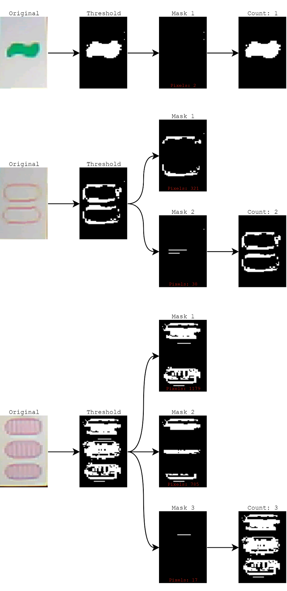
The main problem with our counting algorithm is the initial thresholding step. Under some lighting conditions, the white background pixels don't appear that different from the shape outline, and the built-in automatic threshold function doesn't always seem to return a value that compensates for this. For example, pictured left is an instance where the L threshold value returned (82) causes a lot of the background to persist in the final image.
What ended up working is forgoing thresholding completely and using edge detection instead. I still use the same masking and pixel counting technique as shared in a previous post, but use Canny edge detection to isolate the shape outlines. After some tweaking around with edge detection parameters I obtained the following:

Using edges instead of thresholding based on color proved way more robust for shape counting. With no modification to the other algorithms (fill, color, shape), after three trials two were perfect and one only misclassified the fill for one card:

I may still revisit the fill classification in the future (I think luck is partly to blame for it only messing up once), but it seems for now that the accuracy is high enough that results can be aggregated over multiple trials to filter out spurious incorrect results.
My second personal goal for the week involved designing an enclosure for the final product. Bradley and I wanted to make the system fit into a box with the same form factor as a SET playing card, just for fun. The camera will poke out in the middle of the front, and the screen will be visible on the back.

The front and back halves of the snap-fit enclosure are shown above with models of the LED matrix and OpenMV board included.

The front piece includes some L-shaped brackets to keep the battery in place, and some holes sized for heat-set threaded inserts, which will be used to fasten the OpenMV board securely to the enclosure. The LED matrix will be press fit into a square-shaped cutout so that the screen will be flush with the back surface.

There is a cutout in the front piece where a USB cable can be plugged in and the battery unplugged if needed. We are planning on adding a small switch so that we don't need to plug/unplug the battery every time we need to reset the board.
Next Week
Team Goal: Assemble physical product and improve performance through testing.
Personal Goal: 3D print enclosure and assemble system.
Next week I will be able to take the finished CAD and 3D print our enclosure. Depending on how the tolerances work out, I may need to iterate a couple of times and make small adjustments to get the snap-fit just right. Once the full system is assembled, I'll be able to integrate everything together and use the classification data to control the screen output.


Very good insight with using edge detection over thresholding! I am very excited to see the final CAD product